Shader
The shader panel provides control over the planar shader. This is a capability which colours data along a plane or vector from a given position or offset.
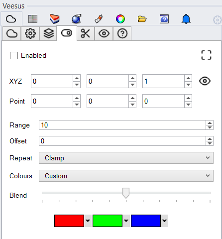
Rhino: The shading is enabled per view. Once enabled/disabled in one view you can apply this to all others by clicking the monitor button:

Once enabled you can change the shaders direction by changing the XYZ values of the normal vector. XYZ should add up to ‘1’ so if your point cloud was aligned true to a planes, the value 0,0,1 would shade on the Z axis (up). If your point cloud is not true to the construction plane then values of 0.054,-0.041,0.998 for example may provide a the alignment (yours will be different if not aligned).
A simpler option is to align the shader to the view direction. Pressing the eye icon will set the XYZ values for you and set the shader “zero” point to be your construction plane position in that view.
Point – Useful for positioning the start point of the shader:
- Rhino - Select a point as per Origin, type "evaluatept" into Rhino command line and copy X,Y,Z values.
- SolidWorks - Select a point as per Origin, under SolidWorks "PropertyManager" copy X,Y,Z values:
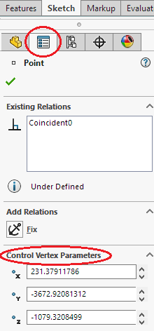
Paste X,Y,Z values into the Veesus point fields
- Revit - Not available at this time.
Range:
The distance over which the shader will calculate values.
Offset:
The distance from the shader zero point to start calculating from. Useful for moving the shader along the axis without changing the construction plane.
Repeat:
How the shader should act once it has gone beyond either the start or end location as calculated by Range + Offset:
- Clamp, continue with first/last colour.
- Stop, don't apply colours beyond range
- Repeat, loop through colours again.
Colours:
You can chose between your own custom colour palette in the shader, or to use the entire RGB hue values.
Blend:
Effect of shader on point colours.